

![[Network] Deep Dive Into OSI 7 Layer Model](https://cdn.hashnode.com/res/hashnode/image/upload/v1698580265351/5794364c-6592-4bcc-82d2-e080288c191a.png?w=1600&h=840&fit=crop&crop=entropy&auto=compress,format&format=webp)
Introduction
In this article, I will talk about what the open systems interconnection (OSI) model is, and what each layer does in the OSI 7 layer model.
Additionally, I will introduce the client-server architecture before we have a look at the OSI model.
Client-Server Architecture
Client-server architecture is a computer model, in which the server delivers requested resources by a client.
The client sends a request, and then the server responds to that request. It is how the client side and server side communicates to transfer the data. The server will wait until the client sends a request.
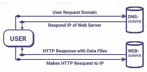
In web development, a user represents a client side. For example, if you fill out a shipping address and other details on the e-commerce platform, and you submit it, you(the client) are sending the POST request to the server.
Now, I just mentioned that the user is on the client side. But...
From user -> to server
From browser -> to server
From server -> to server
These three are possible options as well. The server can send a request to the server. In this case, the client is the server sending a request to another server.
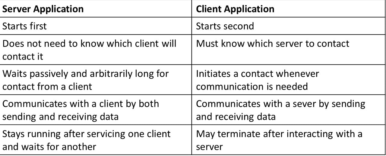
Server vs. Client
OSI 7 Layer Model
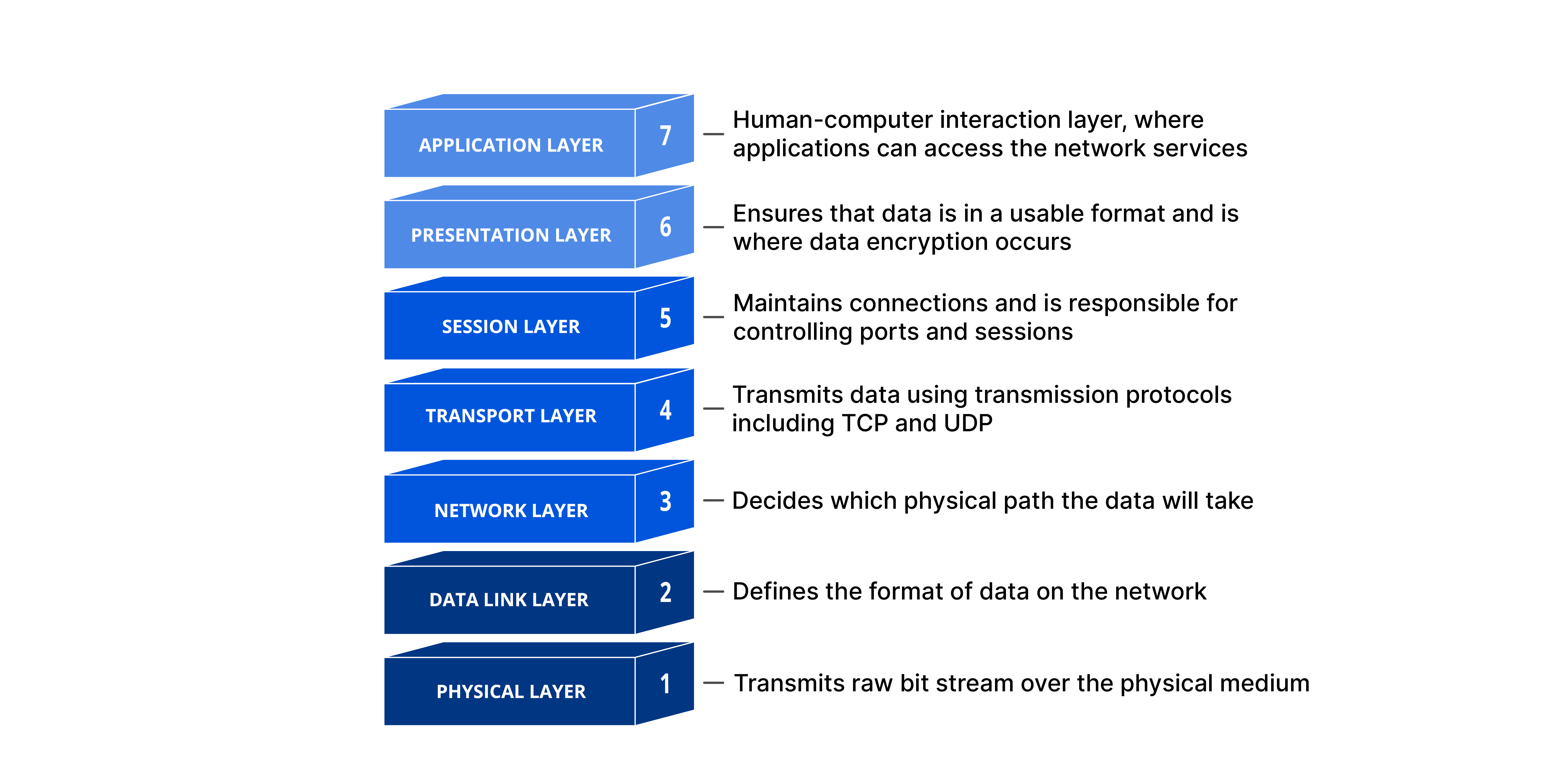
The Open Systems Interconnection(OSI) 7 Layer Model provides a standard for different computer systems to be able to communicate with each other. This model separates a communication system into seven abstract layers.
The 7 layers:
Physical
Data-Link
Network
Transfer
Session
Presentation
Application
If you send a HTTP request from a client side, the data goes from layer 7 to layer 1. When the client receives the response, it goes from layer 1 to layer 7.
Physical Lyaer
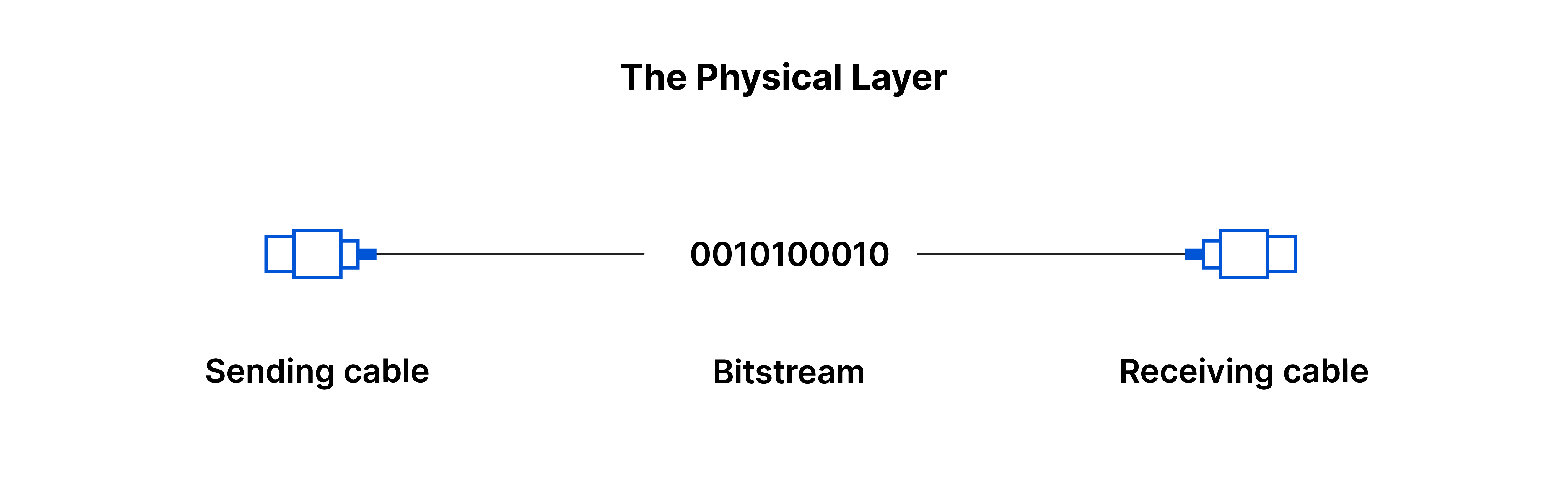
This layer involves the cables and switches, like LAN cables. To transfer data through cable, the LAN card will transfer data into a bit stream, such as 010101000101011110101.
To transfer data successfully, the physical layer of both devices must agree on a signal convention.
Moreover, a parity bit is a method to check if there were any errors occurred. It is the method to append binary bits to make sure that the total count of 1's in the original data is either even or odd.
Data-Link Layer
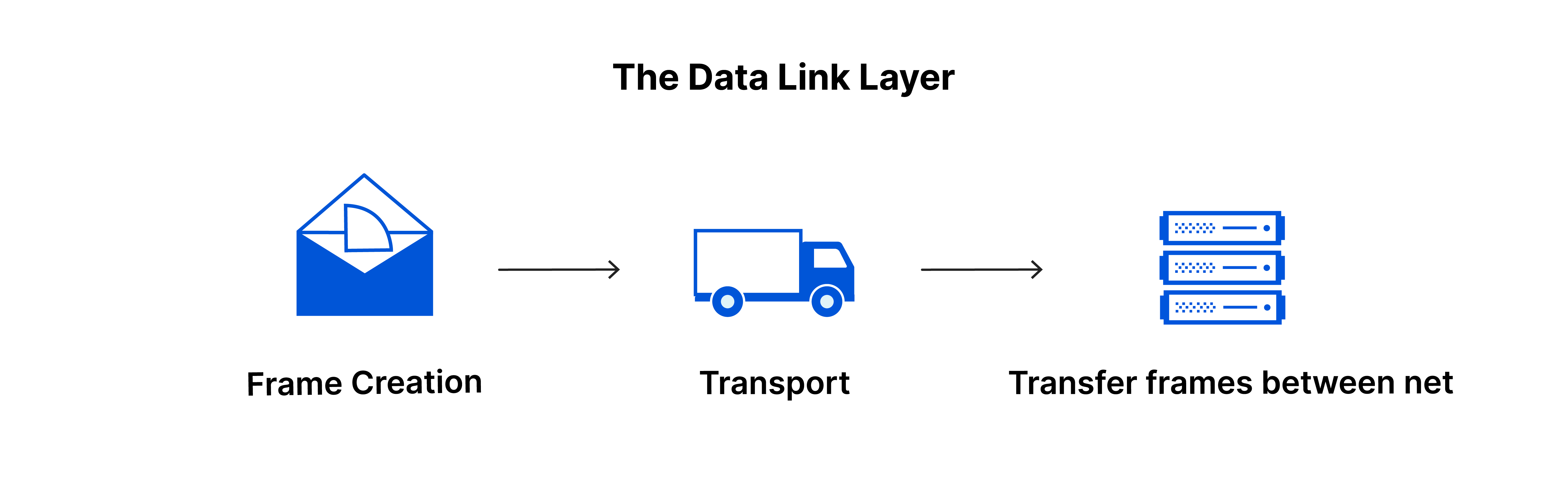
The data link layer facilitates data transfer between two devices on the same network. Moreover, it is responsible for flow control and error control in intra-network communication.
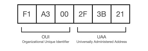
The data-link layer involves MAC address and Wi-Fi. MAC address is 48-bit, and it looks something like this:
In the data-link layer, the data are stored in the frame. The frame looks like this:
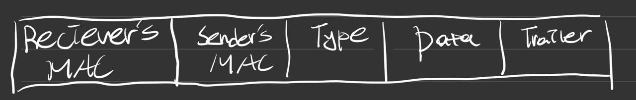
Receiver's MAC(1), Sender's MAC(2), Type(3) - data of data-link layer.
Data(4) - Data of the Network Layer, which is the Layer 3.
Trailer(5) - Trailer of the data-link layer.
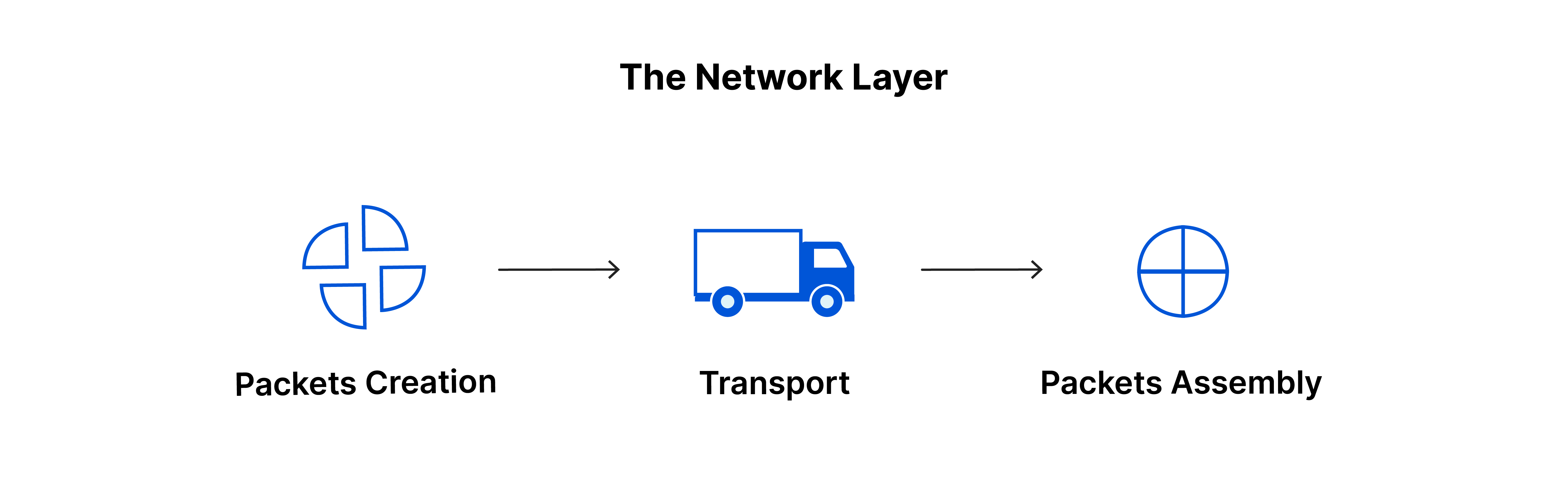
Network Layer
If the two devices communicating are on the same network, then the network layer is unnecessary.
The network layer splits up the segments from the Transport layer into packets, then it combines these packets again.
The network layer also finds the best physical path for the data to reach its destination; this is known as routing.
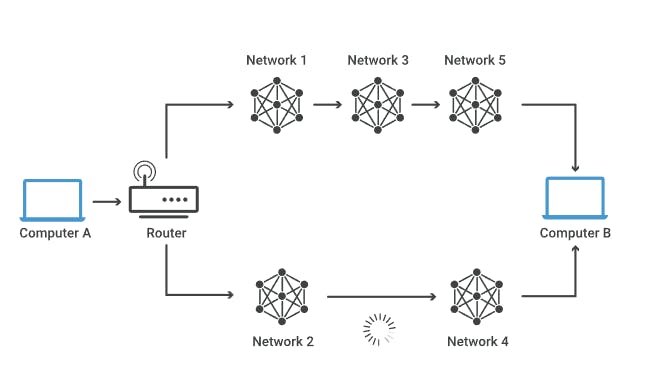
For the data packet from Computer A to arrive at Computer B, which path should we go? The answer is - we don't know, but the network layer will decide. The path through networks 2 and 4 might seem shorter, but the path through networks 1, 3, and 5 might forward the packets faster.
This layer involves an IP address.
IPv4 vs IPv6 (and special IP)
IPv4
32-bit
123.456.78.90 -> an example of IPv4.
Each segment can be from 0 to 255.
0.0.0.0 ~ 255.255.255.255
So, there can be 255^4 = 4228250625 IP addresses, which is less than the total population of humans on the Earth. This is why the IPv6 came out. There is a limited number of IP addresses.
Private IPv4
192.168
172.16 ~ 172.31
starting with 10.
- 10.123.456.789
❌ You cannot communicate with others with private IP addresses.
IPv6
128-bit
IPv4 was 32-bit and provided 4228250625 IP addresses. Now, there are more IP addresses.
Special IP
- 127.0.0.1 -> localhost, which is your local computer.
Transport Layer
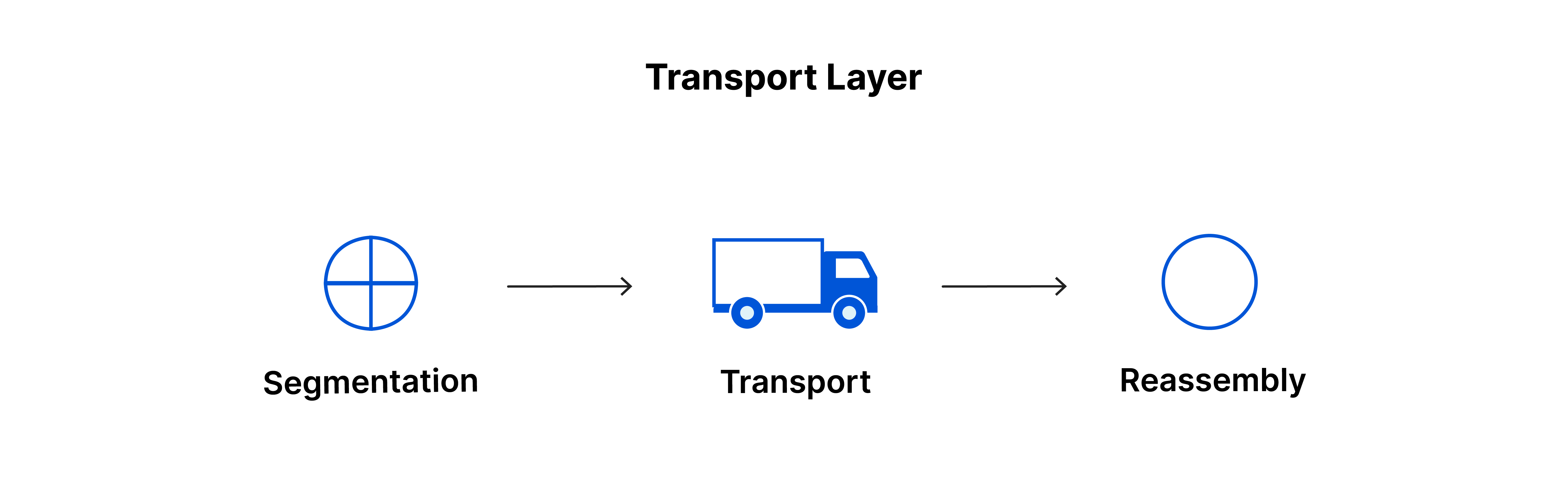
This layer is responsible for end-to-end communication between the two devices. The transport layer breaks the data from the session layer into chunks (segments) before sending it to the network layer. On the receiving device, it will combine the segments into the data.
Segment
In TCP
- The "segment" consists of the TCP header and data. The data is the data from the session layer.
In UDP
- Consists of UDP header and data.
It is also responsible for flow control and error control.
This layer includes TCP/UDP communication and a port.
Some famous port numbers:
443 - HTTPS
80 - HTTP
53 - DNS
22 - SSH
587 - SMTP
Well-known port:
- 0~1023
Port example:
12.345.678.90:80
- HTTP will handle the data of 12.345.678.90.
Session Layer

The session layer is responsible for opening and closing communication between the two devices. The session in the OSI 7 layer model means the time between opening and closing the communication. The session layer ensures that the session stays open long enough to transfer all the data, and close the session at the right moment to avoid wasting any resources.
This layer involves HTTPS (TLS/SSL)
Presentation Layer
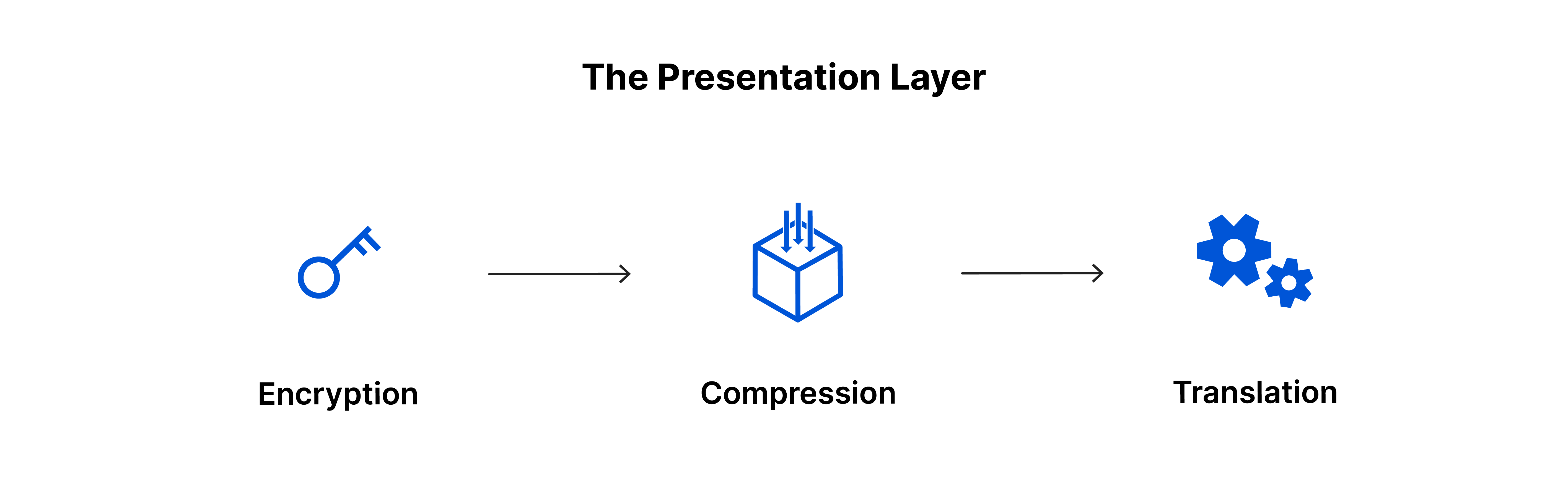
The presentation layer makes the data presentable for the application layer to consume. The presentation layer is responsible for translation, encryption, and compression of data.
The presentation layer involves encoding methods and extensions, such as UTF-8, ASCII, PNG, etc, because it transfers the incoming data into a syntax that the application layer can understand.
Application Layer
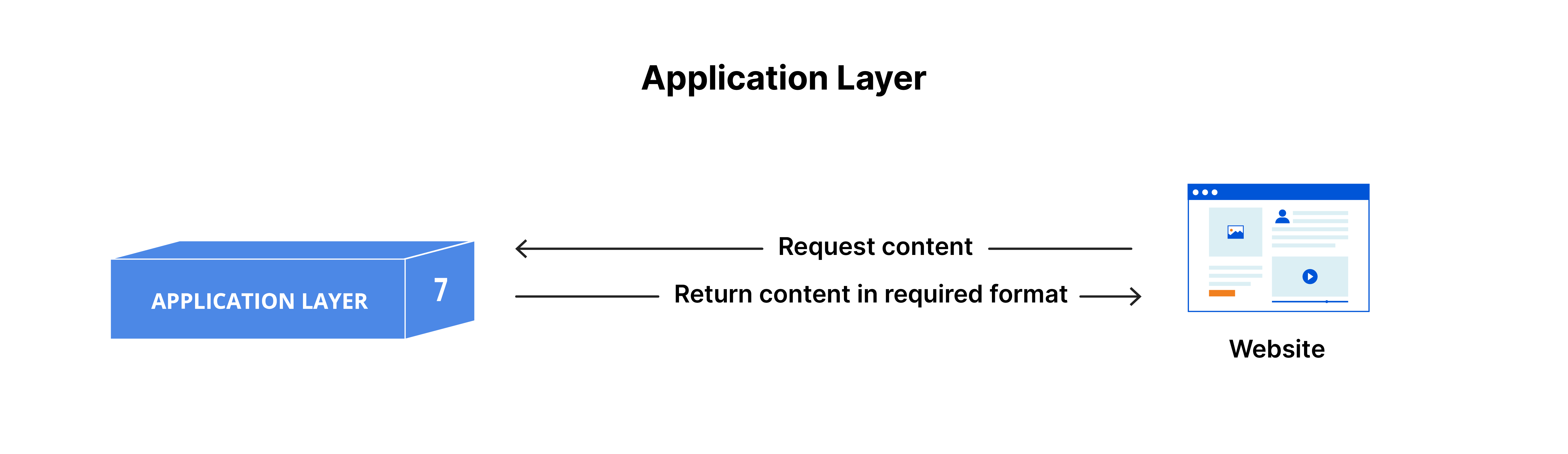
The application layer is the only layer that directly interacts with data from the user. As shown in the diagram, the browser requests the data, and gets the requested content/data from the server.
This layer involves HTTP and SMTP.
Reference
https://www.cloudflare.com/learning/ddos/glossary/open-systems-interconnection-model-osi/